2 Gas Pipelines, compressor and valve stations
One or more compressor stations are needed to keep the required gas flow
in the pipeline. Internal friction will cause a pressure drop along the pipeline
that increases with flow. Thus, the starting pressure must be high enough to
maintain design capacity flow up to the final terminal. If this is not practically
possible, additional compressor stations are needed along the total length.
Typical starting pressure is about 150-250 bar (15-25 MPa). The final
pressure can be as low as 50 bar (5 MPa) at the pipeline terminal end.
The compressors are driven in the same way as explained in the
compressor chapter under production (see Chapter 4.3.3).
68
As an example, about 150 MW in compressor power is required to transport
70 mill scm/day though the 1166 km Langeled pipeline with a starting
pressure of 250 Ormen Lange Nyhamna. The initial section is 42 in, which
increases to 44 in at Sleipner, a little more than halfway
(627 km from
Nyhamna, 540 km from Easington, UK), where the intermediate pressure is
155 bar maximum.
The 1200 km Northstream pipeline from Russia (Portovaya, Vyborg) to
Germany (by Hannover), has two parallel pipes of almost the same
dimensions, pressure and compression power each as Langeled.
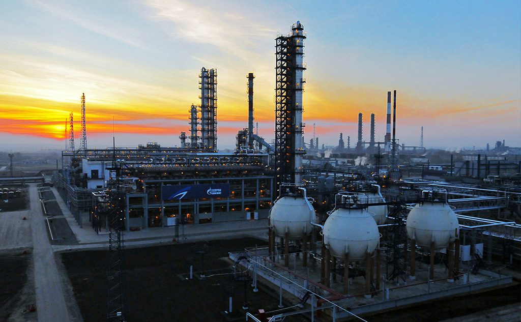
Figure 11. Gas pipeline
Block valve stations (or vine valve stations) are required to allow closure of
off flow at regular intervals to limit accidental release of gas in case of
pipeline rupture. This will be determined by the maximum permissible
released gas volume. A valve station is normally operated by remote
telemetry and in addition to the closing valve, at least contains pressure,
temperature and some level of flow measurement. These will feed back into
the pipeline modeling system. Even if methane (CH4) is lighter than air and
will rapidly rise, other gases such as propane (C3H8) are present in up to 8%
by volume, and are heavier than air. They will sink, and rapidly create a large
volume of combustible gas mixture.
In cases where multiple producers and pipelines feed into a larger pipeline
grid, the pressure balancing to maintain required flow and observe
contractual volume allocations back to individual production sites presents
additional challenges for the pipeline balancing system.
5.4.3 Liquid pipelines, pump and valve stations
Liquid crude or product pipelines are handled much the same way, with
pump stations and block valve stations along the pipeline. However, when
the pipeline goes up or down over hills and mountains, they behave
differently. Liquid, due to the much higher specific gravity, will experience
much higher pressure drops uphill, and increases downhill, than gas. This
often requires additional pumping capacity uphill and corresponding
6
9
pressure-reducing turbines (or braking stations) downhill. In case electrical
power is used, the braking power from the turbine can be fed back into the
grid.
Figure 12. Liquid pipeline
Block valve stations (or line valve stations) are used with many of the same
functions as gas pipelines. It is important to limit accidental spills in case of
rupture of the pipeline, and placement will be determined both by maximum
leak volume as well as city, river or valley crossings and wherever it is
particularly important to prevent spills.
5.4.4 Pipeline management, control and safety
Pipeline management is used to maintain operation and integrity of the
pipeline system. It is usually handled by a SCADA system, which interfaces
with remote locations and collects data and controls valves and process
setpoints. The pipeline management system may include functions such as:
Supervisory control to oversee the operation of the entire pipeline system.
Demand Forecasting to model demand for the coming days across the
system based on parameters like contractual volumes, forecasts from
consumers and producers and meteorology to determine necessary supply
rates and corresponding pressures at various points in the network. Since
the transport delay can be considerable during the off-peak season, delays
can be compensated by pre-charging the line in anticipation of increases, or
allowing pressure to be bled off if a reduction is expected.
Pipeline modeling models the entire pipeline system to account for
pressure, temperature and flow at major checkpoints. Based on this model
the management system can perform:
• Pressure balancing to make certain that pressure setpoints are correct to
meet demand forecasts and avoid potential overload conditions.
70
• Production allocation, which ensures that producers are able to deliver
their contractual volumes into the network.
• Leak detection, which compares actual measured data against dynamic
data predicted by the model. A discrepancy indicates a leak (or a failing
measurement). Simple liquid systems only calculate basic mass balance
(in-out), while an advanced modeling system can give more precise data
on size and position of the leak within a certain response time.
• Pig or scraper tracking is used to track the position of the pig within the
pipeline, both from pig detection instruments and the pressure drop
caused by the pig in the pipeline.
In case of liquid pipelines transporting batches of different products, a batch
transfer system is needed. Based on information on when each product is
injected into the pipeline, and gravity measurement at the receiving end, it is
possible to sequentially transfer different products, such as gasoline and
diesel in the same pipeline. Depending on product characteristics, there will
be an interface section between the two products that widens as the product
moves along the line. This “off spec” product must be discarded at the
receiving end to avoid product degradation. It is often disposed by mixing
with larger volumes of low grade fuel products. This system is often used
with countrywide refined product distribution to terminals